2.1.2. Data Processing
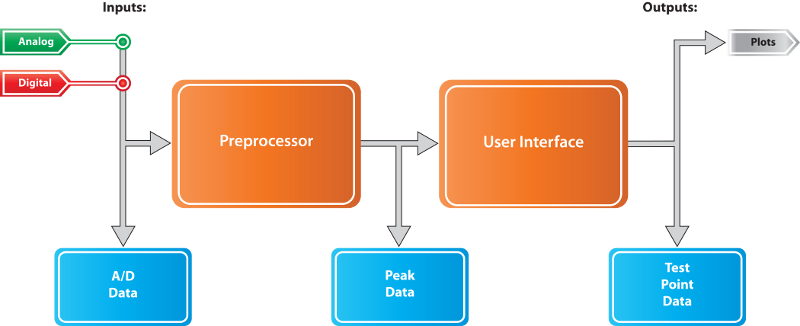
Regardless of its source, the data acquired by APEX DS passes through several processing steps before being stored and displayed. The picture below shows the main stages of this data flow.
The different processing and storage stages may all be implemented by a single instance of the APEX DS application, or by several networked components.
2.1.2.1. Channels, Parameters, Signals and Stats
These terms all describe individual data items propagated through the stages shown above. In the rest of this Manual these terms will be used as follows:
- Channels are the physical inputs of the system used to sample measured data. Channels can be used either as signals or parameters, depending on the acquisition configuration.
- Signals are the high speed dynamic data measurement channels processed and displayed by the system. Signals are always acquired and processed in blocks of samples.
- Parameters are slowly changing measurements. APEX DS acquires (or computes) and records a single value of these for each block of signal data.
- Stats are also slowly changing data values with one sample per acquisition block. But, unlike the parameters above, these are always associated with channels used in the “signal” role. Stats represent per block average values computed from the high speed samples. Examples include stats for DC average, peak to peak value, mean square average (RMS), etc..
2.1.2.2. Data Blocking and Data Rates
APEX DS acquires and processes signal data in blocks of samples. This mode of operation means that there is a fixed relationship between various update rates in the system as explained below:
- Sample rate is the frequency at which APEX DS samples its input data, or at which the already digitized input data was originally sampled (when using digital inputs).
- Block size is the number of input signal samples collected by APEX DS into a data block for time and frequency domain processing. A block of data always contains a number of samples that is a power of 2. A single value of the parameter inputs accompanies the signal data blocks.
- Block rate is the rate at which APEX DS processes the data blocks. This is equal to the sample rate divided by the block size.
- FFT size is the number of samples on which the FFT (Fast Fourier Transform) processing is done. This can be equal to the block size or a multiple of it (by a power of 2). If the FFT size is larger than the block size, APEX DS performs overlapped FFT-s on each input data block by joining it with the necessary number of adjacent blocks to collect the required number of samples. This means that in overlapped mode each data sample is processed multiple times.
- Plot refresh rate is the rate at which the plots are redrawn on the APEX DS graphical user interface. This can be as high as the block rate, but the user interface may perform redraws slower if the performance of the graphics hardware is insufficient.
2.1.2.3. Multiple Sample Rates
APEX DS supports data acquisition at different sample rates by providing per channel over-sampling or down-sampling in steps that are powers of 2 between 1/16 and 16. Note that most supported acquisition devices do not have the hardware features necessary to provide independent sample rates on on a per channel basis. This means that in most applications the oversample of down-sample ratios must be set the same for all channels of a single device. However, multiple sample rate configurations are still possible if the system contains more than a single acquisition device.
2.1.2.4. Processor Data Flow
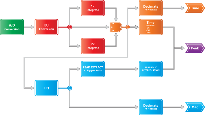
The data processor of an APEX DS acquisition system processes data according to the flow chart below.
Channels are continuously sampled by the A/D Conversion process and samples are grouped into data packets for each block. The EU Conversion (Engineering Unit Conversion) stage scales the input data using coefficients established during acquisition setup, and produces the time domain data packets propagated to the APEX DS user interface. This stage can optionally perform integration or differentiation on the input signal too. The scaled data packets are also used as inputs to the spectral analysis phase of the data processing. This involves performing an FFT (Fast Fourier Transform) on the data and extracting the biggest frequency domain peaks. The extracted peaks are further enhanced by performing parabolic interpolation on them. This process will generate enhanced spectrum peaks up to an user configured maximum count. However, the final count may be lower depending on processing thresholds and the actual input data.
Alternatively, some channels may be processed as parameters. This means computing a single scalar value from a block’s worth of high speed input samples. There are different ways this processing can occur:
- Regular Parameter values are computed as the DC average of the input block’s samples.
- Speed Parameter values are computed by comparing the input samples to a threshold value in order to detect the location of tachometer pulses in the input. The average distance between the detected pulses will then be converted to a rotational speed (RPM) value. For channels used this way the data processor also generates outputs that represent the location of the detected pulses. Speed parameter processing has several user configurable options.
- IRIG Time Code channels are processed by assuming that the input samples are from a 1kHz carrier IRIG-B 120 waveform. If a valid time code signal is detected then the resulting time code value is used to time tag all input data for the current block.
2.1.2.5. Optional Processing Steps
As shown on the image in the section above, there are various stages of the data processing where it is possible to insert optional processing steps. This is done by adding one or more plugin modules to the processing chain via an interpreted text line inserted into the APEX DS data processor configuration. Plugins can be inserted at one or more of the following stages:
- Raw Plugins work directly on the incoming raw input data before anything else. They can generate updated raw samples that will replace the original input for the purposes of further processing. Unlike plugins at later stages, raw plugins may require access to overlapped data. This means that raw input data from the previous and next blocks will also be available for computing the updated raw samples of the current block. Typical use cases of raw plugins include FIR filters, spike filters, etc..
- Time Plugins work on time domain samples after the EU conversion step. They can generate updated time domain samples that will replace the original input for the purposes of further processing. Typical use cases of time plugins include IIR filters, defining and computing “non standard” stats, etc..
- FFT Plugins work on the final results after all “standard” processing steps are done. They can only define and compute additional stat values or update the status flags of the extracted FFT peaks. Typical use cases of FFT plugins are noise tagging filters.
- Peak Plugins are essentially the same as the FFT plugins above. The only difference is that they do not require access to processed time domain or FFT samples, only to the extracted peak data. This makes them usable in some situations where the full per block data set is not available.
Note
Channels processed as parameters or IRIG time codes will only execute their raw plugins.
2.1.2.6. Duplicated Channels
The APEX DS data processor allows duplicating any of its input channels in order to process the secondary copy with different settings. Additionally, duplicate channels themselves can be duplicated again. There is no limit on the number of duplicates created from any channel. Duplication can occur at any of the following four stages:
- At the raw input data stage.
- At the raw data stage after any raw plugins.
- At the EU converted time domain stage before any time plugins.
- At the EU converted time domain stage after any time plugins.
Any step in the “regular” processing sequence that follows the stage of duplication will be performed and be fully configurable in the context of the duplicated channel.
Note
There are certain duplicated channel combinations that are invalid. These are listed below:
- Duplicating a channel marked as “unused”.
- Duplicating a channel used as IRIG or parameter at either one of the “time” stages.
- Using a channel duplicated at either of the “time” stages as IRIG or parameter.
- Adding raw plugins to a channel duplicated at the raw plugin stage from its source.
Duplicate channels will “inherit” their source channel’s sample rate.
2.1.2.7. Computed Channels or Parameters
The third way new non-input signal channel or parameter items can be defined in APEX DS is to specify them as the result of some arithmetic expression. The operands of these expressions can be constants, parameter values, signal channels or their stats. Parameter expressions are evaluated on scalar values where channel operands are replaced with their per block average. Signal channel expressions are evaluated at the sample rate equaling that of their highest sample rate channel operand.
Note
The value used for channel operands of the “compute” expressions is always the final result of the time domain processing, i.e. the output of the “time plugin” stage.
Computed channels can be duplicated too!
Computed channels can only be used in the “signal” role, it is not possible to process them as IRIG or parameter.
2.1.2.8. Processing Delay
Some of the processing steps described above require access to earlier and later data blocks in order to compute the current one. The processing delay and the total number of blocks required before a single output block is produced are the sum of the following two requirements:
- Raw Plugins may require one previous and one future raw data block.
- Overlapped FFT processing requires N/2 past and future EU processed data blocks for an overlap of N. For example, an overlap of 8 will require 4 past and future blocks besides the current one.
These data block buffering and delay requirements will manifest in different ways in members of the DS application suite. In APEX DS the processing delay will contribute to the delay between when a sample was acquired and when it can be monitored on the user interface. In APEX DV the playable range of the input file’s blocks will be “trimmed” on both ends by the required total processing overlap.
2.1.2.9. Data Packets
The data resulting from the above processing steps is split into several separate sequences of data packets:
- Raw Packets are unmodified copies of the input data. These are not sent to the user interface, but can be optionally recorded.
- Time Packets contain the input data scaled in engineering units. The stream of these packets may be decimated before storage by using only every Nth packet.
- Magnitude Packets contain the absolute value of the FFT results. The stream of these packets may be decimated before storage by using only every Nth packet.
- Peak Packets contain summary data for each data block. These include time domain statistics such as peak to peak and RMS values and the extracted and parabolic interpolated FFT peaks. These packets are all stored and propagated to the user interface to guarantee that the displayed top responses are always accurate.
- Parameter Packets contain once per block values. These can be computed from channels that are configured as parameters or received from external sources. These packets are all stored and propagated to the user interface to guarantee that the parameter histories are always accurate.
Various combinations of these packets are stored in different versions of the data files that can be recorded and replayed by the applications of the APEX DS suite.

